- 您现在的位置:买卖IC网 > Sheet目录319 > CHIPPROG-G4 (Phyton Inc)PROGRAMMER GANG 4 SOCKET
�� �
�
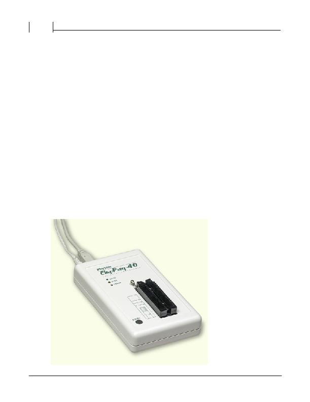
�ChipProg� Family� Brief� Description�
�4.� Can� program� target� devices� in� the� programmer� ZIF� socket� as� well� as� the� devices� installed� in� the�
�equipment� (ISP� mode).�
�5.� ChipProg-48� tools� can� be� driven� from� multiple� USB� ports� of� one� computer� (or� via� a� USB� hub)� to�
�provide� concurrent� programming� of� multiple� devices� of� the� same� type.�
�6.� Has� a� button� for� fast� manual� launch� of� any� single� operation� or� a� bunch� of� operations.�
�7.� Has� three� LEDs� for� displaying� the� programming� status� (“Good”,� “Busy� ”,� “Error”).�
�17�
�2.2.2�
�2.2.3�
�Hardware characteristics�
�1.� The� programmer� has� a� 48-pin� ZIF� socket� with� a� lever� that� enables� the� insertion� and� clamping� of� any�
�DIP-packed� devices� with� the� package� width� from� 300� to� 600� mil� (7.62� to� 15.24� mm)� and� with� the�
�number� of� leads� up� to� 48.�
�2.� Adapters� for� programming� devices� in� the� SDIP,� PLCC,� SOIC,� SOP,� PSOP,� TSOP,� TSOPII,� TSSOP,�
�QFP,� TQFP,� VQFP,� QFN,� SON,� BGA,� CSP� and� other� packages� are� available� from� Phyton� and� many�
�third� parties.�
�3.� The� programmer� is� built� on� the� base� of� a� very� fast� and� productive� 32-bit� embedded� microcontroller� and�
�FPGA.� These� resources� allow� adding� new� targets� to� the� device� list� by� a� simple� software� update.�
�4.� Most� timing-critical� parts� of� the� programming� algorithms� are� implemented� on� the� FPGA� devices� and�
�do� not� involve� any� operations� on� the� embedded� microcontroller� that� would� slow� down� the� programming�
�speed.�
�5.� Implementation� in� the� FPGA� devices� logical� drivers� enables� outputting� logical� signals� of� any� level� (low,�
�high,� Pullup,� Pulldown� and� external� clock� generator)� to� any� pin� of� the� programming� ZIF� socket.�
�6.� The� tool� hardware� features� 10-bit� digital-to-analog� converters� for� accurate� settings� of� the� analog�
�signals.�
�7.� The� tool� hardware� enables� accurate� programming� of� the� rising� and� falling� edges� of� the� generated�
�analog� signals.�
�8.� The� tool� hardware� automatically� adjusts� the� generated� analog� signals.�
�9.� The� generated� analog� signals� for� both� the� target� supplying� and� programming� can� be� outputted� to� any�
�pins� of� the� device� being� programmed.�
�10.The� tool� hardware� can� connect� any� pin� of� the� device� being� programmed� to� the� “Ground”� level.�
�11.The� tool� hardware� checks� if� every� pin� of� the� target� device� is� reliably� fixed� by� a� ZIF� socket’s� contacts�
�(“bad� contact”� checking).�
�12.The� tool� hardware� protects� itself� and� the� target� device� against� incorrect� insertions� and� other� issues�
�that� cause� a� sharp� increase� in� the� currents� though� the� target� device� circuits.� This� “over� current”�
�protection� is� very� fast� and� reliable.�
�13.The� target� device� pins� are� protected� against� the� electrostatic� discharge.�
�14.The� tool’s� hardware� has� a� programmable� clock� generator.�
�15.�
�Software features�
�1.� Works� under� control� of� Windows� 95/98/ME/2000/XP/Vista.�
�2.� Friendly,� intuitive� graphic� user� interface.�
�3.� Includes� a� set� of� basic� commands:� Blank� Check,� Erase,� Read,� Write,� Verify,� Lock,� Set� Configuration�
�Bits,� Data� Memory� Support,� etc.,� executed� by� a� single� mouse� click� or� via� menu.�
�4.� Enables� programming� a� batch� of� the� commands� above� executed� one� after� one� either� by� a� manual�
�start� or� by� a� mouse� click� or� automatically� upon� the� device� insertion� into� the� programming� socket.�
�5.� Allows� serialization� of� the� programming� devices� with� auto� incrementing� the� device� numbers� and�
�storing� a� serialization� log.�
�6.� The� program� can� calculate� checksums� of� the� selected� data� array� and� then� write� the� checksum� into� a�
�specified� memory� location� of� the� target� device.� Several� methods� of� the� checksum� calculation� can� be�
�?� 2010� Phyton,� Inc.� Microsystems� and� Development� Tools�
�发布紧急采购,3分钟左右您将得到回复。
相关PDF资料
CHUSBWB-2
BATT CHARGER AA/AAA W/2AAA CELLS
CK-S6-SP623-G
BOARD DEV S6 WITH TX
CK-V6-ML628-G
KIT VIRTEX-6 CHAR ML628
CLSD004
LED DRIVER PROGRAMMER W/CABLE
CMC484812
RACK STEEL 12X48X48 GRY
CMCQP3
PANEL INNER 25.59X15" GREY
CML12C32SLK
KIT STUDENT LEARNING 16BIT HCS12
CMR-8040
RACK CABLE MANAGMNT OPEN ASSMBLY
相关代理商/技术参数
CHIPPROG-G41
功能描述:PROGRAMMER GANG 4 SOCKET RoHS:是 类别:编程器,开发系统 >> 独立编程器 系列:- 产品目录绘图:CHIPPROG-G4 标准包装:1 系列:- 类型:成组编程器 适用于相关产品:EEPROM,EPROM,FLASH,MCU,NVRAM,PLD 所含物品:编程器,线缆,CD 产品目录页面:598 (CN2011-ZH PDF) 相关产品:AE-TS56-16I-3-ND - ISP CABLEADAPTER 14-PIN HEADERAE-TS40N-ND - ADAPTER SOCKET 40-TSOP TO 40-DIPAE-TS32N-ND - ADAPTER SOCKET 32-TSOP TO 32-DIPAE-TS28-ND - ADAPTER SOCKET 28-TSOP TO 28-DIPAE-T44-P16-ND - ADAPTER SOCKET 44-QFP TO 40-DIPAE-T44-I51/505-ND - ADAPTER SOCKET 44-QFP TO 40-DIPAE-SS56-16I-ND - ADAPTER SOCKET 56-SSOP TO 40-DIPAE-SP8U-ND - ADAPTER SOCKET 8-SSOP TO 8-DIPAE-SP28U2-ND - ADAPTER SOCKET 28-SSOP TO 28-DIPAE-SP28U1-ND - ADAPTER SOCKET 28-SSOP TO 28-DIP更多...
CHIPPROG-ISP
功能描述:PROGRAMMER IN-SYSTEM UNIVERSAL RoHS:是 类别:编程器,开发系统 >> 内电路编程器、仿真器以及调试器 系列:- 产品变化通告:Development Systems Discontinuation 19/Jul/2010 标准包装:1 系列:* 类型:* 适用于相关产品:* 所含物品:*
CHIPS CAPACITOR 0.015UF 50V CERAMIC
制造商:AVX Corporation 功能描述:CHIPS CAPACITOR 0.015UF50VCERAMIC*NIC*
CHIPS-IN-DIPS
制造商:未知厂家 制造商全称:未知厂家 功能描述:ASIC
CHIPT1593CSE6327X1SA1
制造商:Infineon Technologies AG 功能描述:RF SILICON MMIC - Gel-pak, waffle pack, wafer, diced wafer on film
CHIPV6
制造商:JDSU 制造商全称:JDS Uniphase Corporation 功能描述:The industrya??s most compact 100 G test solution
CHIS-24
制造商:Mencom 功能描述: